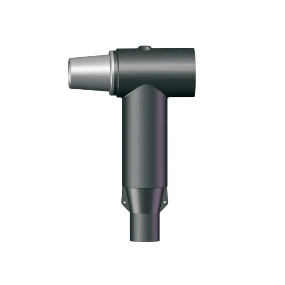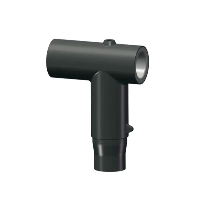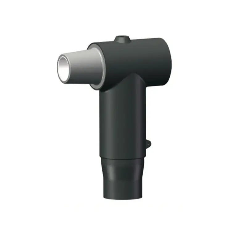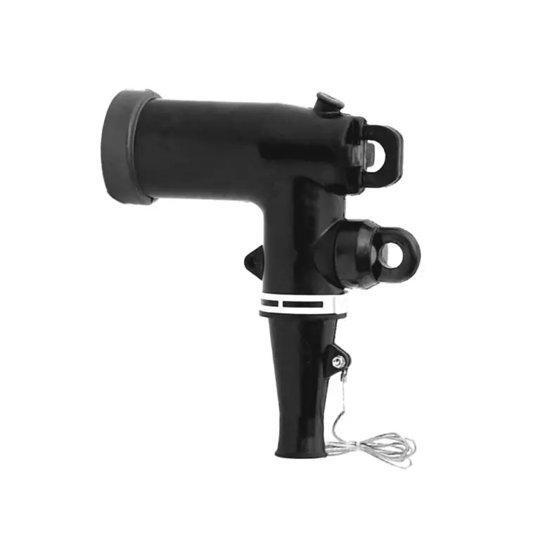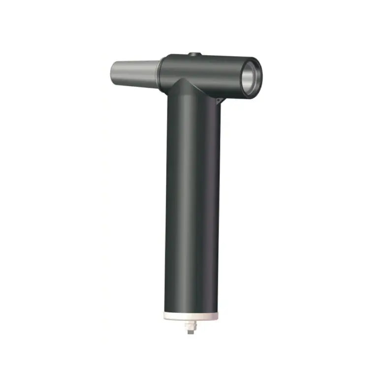
The T-Body connectors are used to terminate polymeric cable to
dead front apparatus such as transformers, switchgear and other
equipments. It can be used at 24kV systems and indoor or outdoor
applications. Also it is used for all polymeric cable types. (XLPE, EPR) with copper or bimetal conductors
Tests conducted in accordance with IEC 60502-4.
· Partial discharge minimum extinction voltage - 20kV
· AC 60Hz for 1min(kV crest) - 54kV
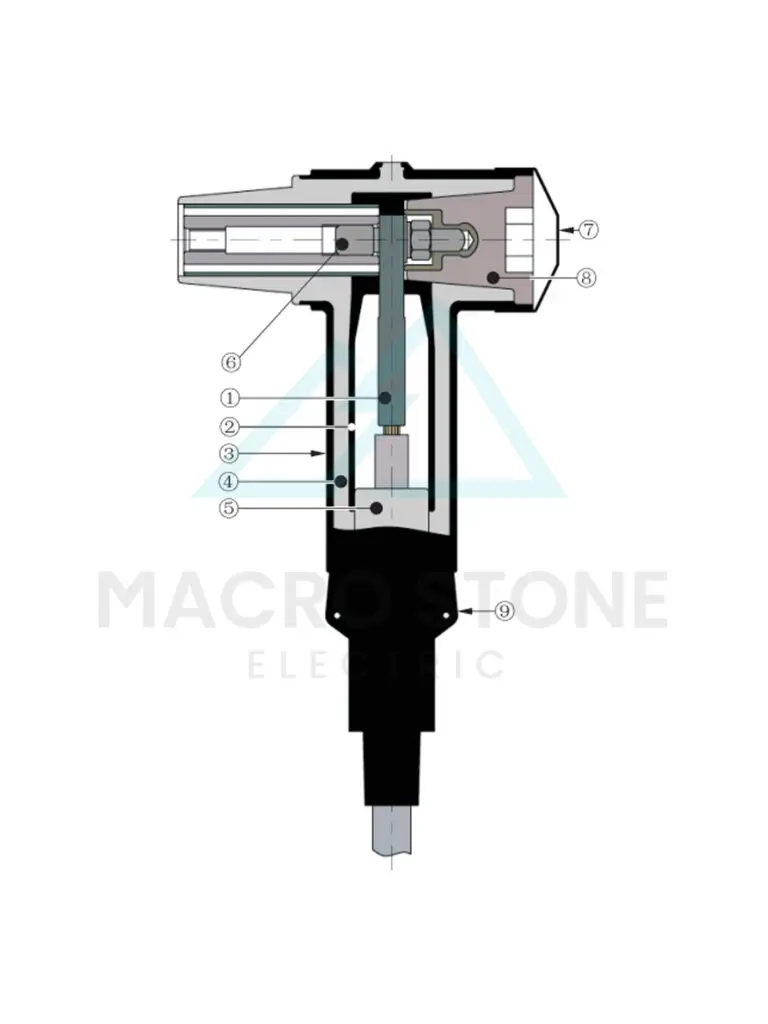
1. COMPRESSION LUG
Optional Copper, or Standard Bi-Metal, compression lug is sized to ensure a cool running connection with maximum current transfer.
2. SEMICONDUCTING INSERT
Precision molded peroxide cured semiconducting insert provide scorona-free electrostatic shielding of the compression connector.
3. SEMICONDUCTING SHIELD
Precision molded peroxide cured semiconducting shield provides ground shield continuity.
4. INSULATION LAYER
High quality peroxide cured EPDM Insulation is mixed and formulated in-house for complete control of rubber characteristics.
5. CABLE ADAOTER
Molded cable adapter, sized to fit cable insulation diameters from(17.2mm~35mm)0.677inches to 1.378 inches, provides stress relief for the terminated cable.
6. STUD
Zinc plated,threaded steel stud.
7. CONDUCTIVERUBBER CAP
Provide a complete grounding system.
8.INSULATING PLUG
Molded epox yinsul a ting plug provides excellent electrical, thermal andmechanical reliability.
9. DRAIN WIRE TAB
Drain wire tabs provide a convenient point to connect drain wire to ensure grounding of the connector shield.
- MS
- 24kV 630A
- DRT
- X (Cable Range Code)
- Y (Conductor Code)
- Z (Enter C if a plated Copper Connectoris Desired, Bi-metal are standard)
Note : Bi-metal lug for use on copper and aluminum conductors. Copper lug for use on copper conductors only.
| Voltage Class | 24kV |
|---|---|
| AC for 5 Minute | 54kV |
| BIL and Full Wave Crest | 125kV |
| Partial discharge minimum extinction voltage | 20kV |
| Thermal Short Circuit (Conductor, 2 sec.) | 23kA/2s |
| Dynamic Short Circuit (Conductor, 10 sec.) | 82kA/10ms |
| Screen leakage current | less than or equal to 0.5mA |
| Cable Range Code | Inches | Millimeters |
|---|---|---|
| A | 0.677-0.807 | 17.2-20.5 |
| B | 0.717-0.846 | 18.2-21.5 |
| C | 0.815-0.945 | 20.7-24 |
| D | 0.933-1.063 | 23.7-27 |
| E | 0.992-1.122 | 25.2-28.5 |
| F | 1.130-1.260 | 28.7-32 |
| G | 1.248-1.378 | 31.7-35 |
| Conductor Code | Conductor Size (mm²) |
|---|---|
| 01 | 25 |
| 02 | 35 |
| 03 | 50 |
| 04 | 70 |
| 05 | 95 |
| 06 | 120 |
| 07 | 150 |
| 08 | 185 |
| 09 | 240 |
| 10 | 300 |