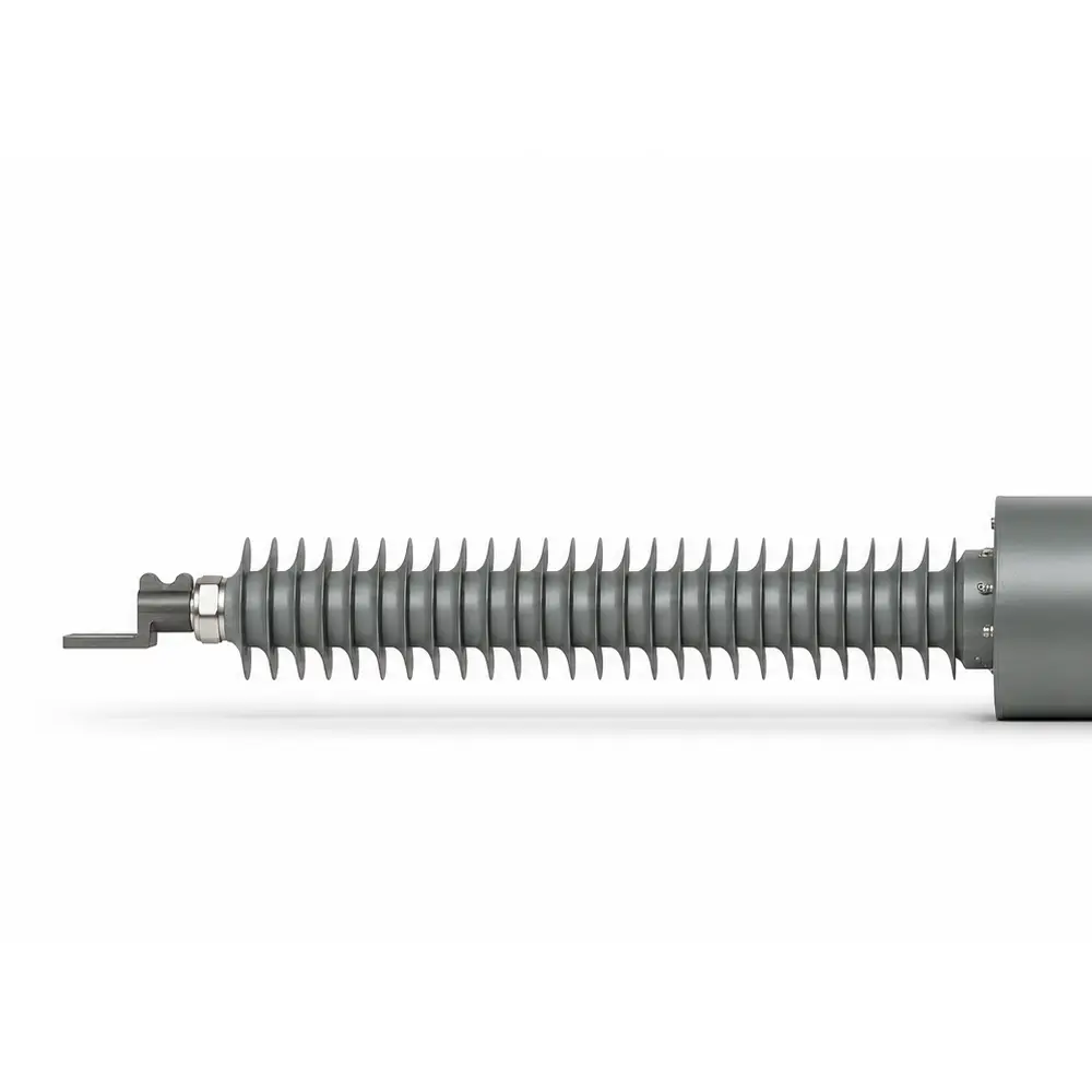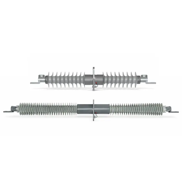
This product consists of the following main components: current-carrying conductor, capacitive core, outer sheath, sheds, secondary winding, current transformer (CT) housing, and end fittings.
A test tap is provided on the current transformer housing. It is opened for partial discharge and dielectric dissipation factor measurements and must be reliably grounded during normal operation.
Both ends of the product are equipped with equipment terminal connectors.
·GB/T 4109-2022; IEC 60137:2017 – Insulated Bushings for Alternating Voltages Above 1000 V.
·GB 20840.2-2010; IEC 61869-2:2012 – Instrument Transformers – Part 2: Additional Requirements for Current Transformers.
Model: FCRG-L-X/Y
- F: Composite main insulation
- C: Wall bushing
- R: Capacitive type
- G: Dry-type insulation with silicone rubber external insulation
- L: LRB Through-type current transformer
- X: Rated voltage, in kV
- Y:Rated current, in A
·Dry-type composite capacitive insulation, oil-free, porcelain-free and gas-free.
·Excellent resistance to pollution and moisture.
·Ambient Temperature: -50°C to +50°C
·Altitude: Designed for an installation altitude of 1000 m. For installations above 1000 m, corrections shall be made in accordance with GB 311.
·Pollution Class: Class IV for outdoor applications and Class III for indoor applications.
(Special requirements shall be specified separately.)
·Applicable Rated Voltage Levels: 12 kV, 24 kV, 40.5 kV, 72.5 kV, 126 kV.
·Eated Primary Current: ≤ 2,500 A
· 60-second Power Frequency Withstand Voltage Test
·Partial Discharge (PD) Test
·Dielectric Dissipation Factor and Capacitance Measurement
· Accuracy Test
· Voltage-Current Characteristic Test (V-I Characteristic Test)
· Polarity Test
· Open-Circuit Voltage Test
· Secondary Winding DC Resistance Test
1. The relevant lead of the capacitive insulation system must be reliably grounded during normal operation.
2. The secondary circuit must never be open-circuited during operation.
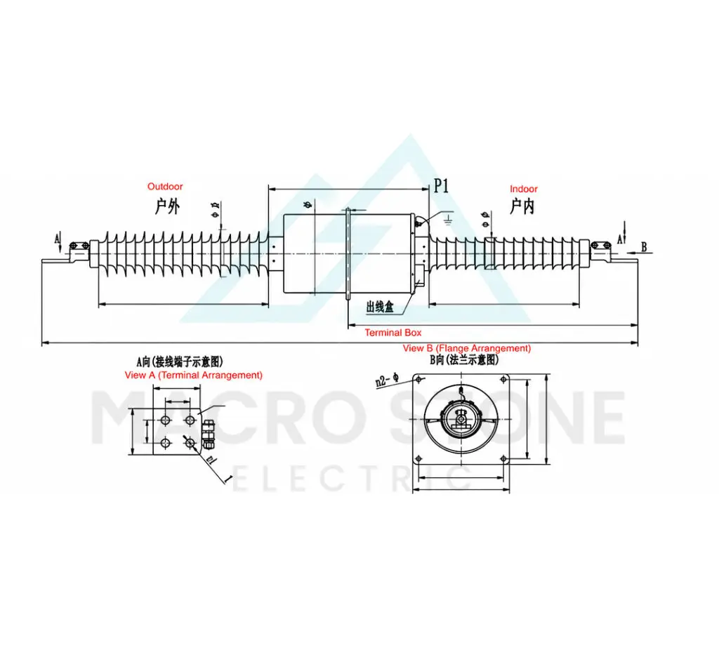
3. When placing an order, the direction of the P1 side (current entry direction) must be clearly specified.
| Highest Voltage for Equipment (Um), kV | Rated Voltage, kV | Power Frequency Withstand Voltage, kV | Lightning Impulse Withstand Voltage (Peak), kV | Partial Discharge Level at 1.05Um/√3, pC | Dielectric Dissipation Factor | Rated Short-Time Thermal Current, kA | |
|---|---|---|---|---|---|---|---|
| Dry | Wet | ||||||
| 12 | 10 | 28 | 28 | 75 | ≤5 | ≤0.003 | 25Ir |
| 24 | 20 | 50 | 50 | 125 | ≤5 | ≤0.003 | 25Ir |
| 40.5 | 35 | 95 | 80 | 200 | ≤5 | ≤0.003 | 25Ir |
| 72.5 | 66 | 160 (140) | 140 | 350 (325) | ≤5 | ≤0.003 | 25Ir |
| 126 | 110 | 230 (185) | 230 (185) | 550 (450) | ≤5 | ≤0.003 | 25Ir |
Temperature Rise: Not exceeding 85 K
| Model | Overall Length (L) | Indoor Overall Length (L1) | Indoor Clearance (L2) | Outdoor Clearance (L3) | Max. Outside Diameter (φD1) | Max. Outside Diameter (φD2) | Mounting Flange Dimensions | Terminal Dimensions (L5) | |||||||
|---|---|---|---|---|---|---|---|---|---|---|---|---|---|---|---|
| L4 | L7 | L8 | n2-φd2 | φD | L5 | L6 | t | n1-φd1 | |||||||
| FCRG-L-40.5/630~1250 | 1560 | 725 | 300 | 400 | 180 | 180 | 430 | 400 | 350 | 4-φ18 | 340 | 80 | 40 | 12 | 4-φ14 |
| FCRG-L-40.5/1500~2500 | 1610 | 750 | 300 | 400 | 180 | 180 | 430 | 400 | 350 | 4-φ18 | 340 | 100 | 50 | 15 | 4-φ18 |
| FCRG-L-72.5/630~1250 | 2420 | 1170 | 620 | 720 | 220 | 180 | 650 | 400 | 350 | 4-φ18 | 340 | 80 | 40 | 12 | 4-φ14 |
| FCRG-L-72.5/1500~2000 | 2470 | 1185 | 620 | 720 | 220 | 180 | 650 | 400 | 350 | 4-φ18 | 340 | 100 | 50 | 15 | 4-φ18 |
| FCRG-L-72.5/2500 | 2510 | 1205 | 620 | 720 | 220 | 180 | 650 | 400 | 350 | 4-φ18 | 340 | 125 | 60 | 20 | 4-φ18 |
| FCRG-L-126/630~1250 | 3120 | 1525 | 980 | 1060 | 220 | 180 | 650 | 400 | 350 | 4-φ18 | 340 | 80 | 40 | 12 | 4-φ14 |
| FCRG-L-126/1500~2000 | 3170 | 1550 | 980 | 1060 | 220 | 180 | 650 | 400 | 350 | 4-φ18 | 340 | 100 | 50 | 15 | 4-φ18 |
| FCRG-L-126/2500 | 3210 | 1570 | 980 | 1060 | 220 | 180 | 650 | 400 | 350 | 4-φ18 | 340 | 125 | 60 | 20 | 4-φ18 |