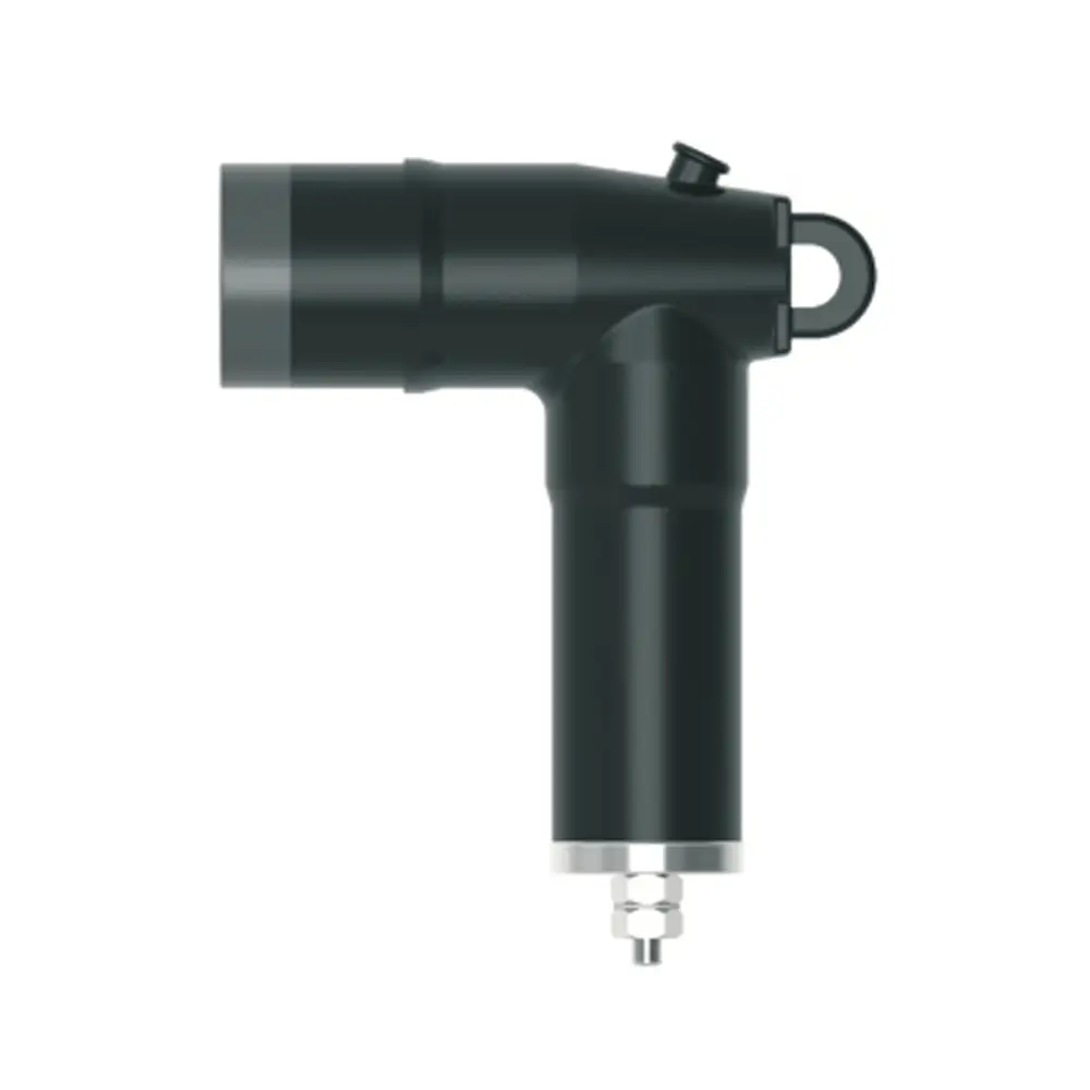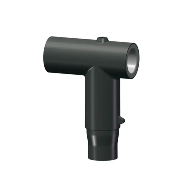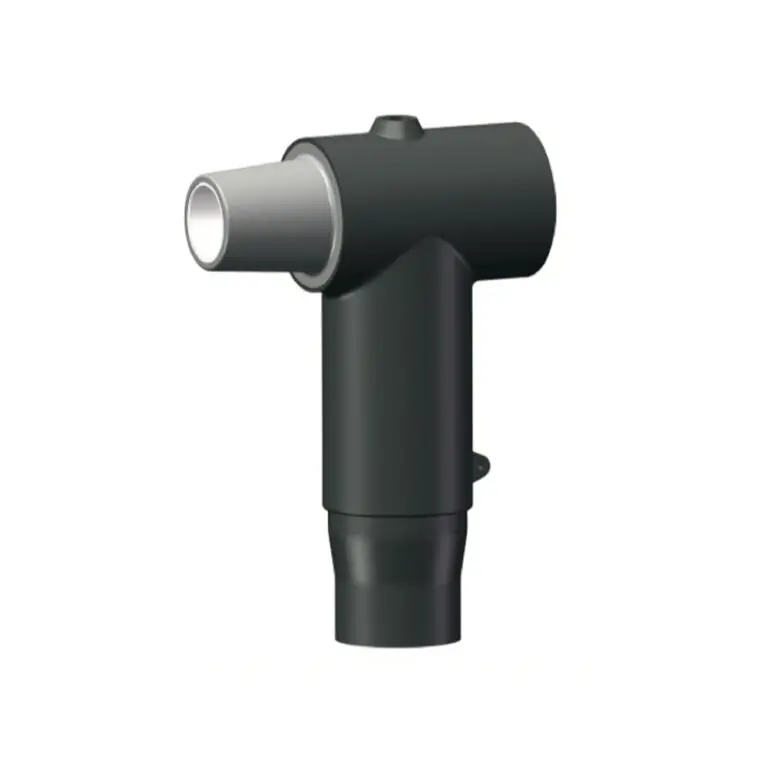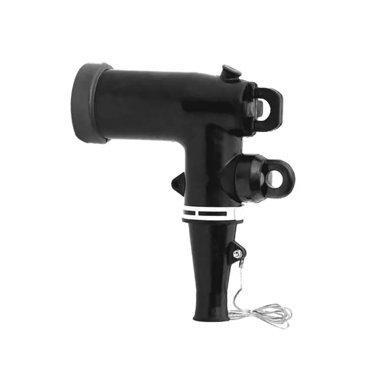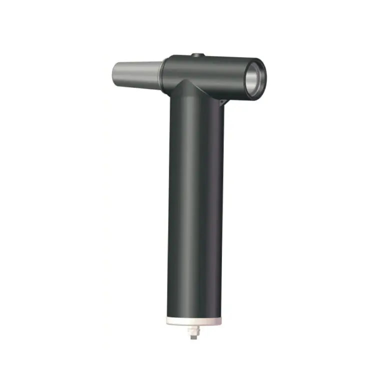
The elbow arrester combines a metal-oxide varistor module within a rubber elbow to provide overvoltage protection for the system. The arrester elbow housing design meets the IEEE 386 standard. It is molded from high-quality peroxide-cured insulating and semi-conducting rubber and is fully interchangeable with competitors' products that also meet IEEE Standard 386.
Elbow arresters are used on underground systems in pad-mounted transformer and entry cabinets, vaults, switching devices, and other enclosures to provide shielded dead-front arrester protection. Installing elbow arrester at both ends of an open point on a loop system and the end of a radial system protects equipment and extends cable life.
. Provides fully shielded deadfront arrester protection.
. Metal (zinc) Oxide Varistor (MOV) gapless design.
. EPDM insulation rubber molded around MOV module.
. No minimum phase clearance requirements.
. 100% electrically tested at factory.
Tests conducted in accordance with IEEE/ANSI Standard 386 and IEEE Std C62.11.
· Partial discharge minimum extinction voltage - 15kV
· AC 60Hz for 1min(kV crest)-34kV
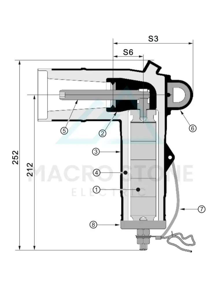
1. METAL OXIDE RESISTOR ELEMENTS
At wo-terminal resistive element, composed of an electronic semiconductor and suitable contacts, that has a markedly nonlinear volt-amperecharacteristic.
2. SEMICONDUCTING INSERT
Precision molded peroxide-cured semiconducting insert providescorona-free electrostatic shielding of the compression connector.
3. SEMICONDUCTING SHIELD
Precision molded peroxide-cured semiconducting shield provides ground shield continuity.
4. INSULATION LAYER
High-quality peroxide-cured EPDM Insulation is mixed and formulatedin-house for complete control of rubber characteristics.
5. LOADBREAK PROBE
Tin-plated copper probe with arc-extinguishing tip allows for dependable switching operations.
6. PULLING EYE
Stainless steel pulling eye for hot stick switching operations.
7. DRAIN WIRE TAB
Drain wire tabs provide a convenient point to connect drain wire to ensure grounding of the connector shield.
8. STEEL CAP
Portion of an arrester in which each end of the unit is terminated with an electrode that is exposed to the external environment.
- MS
- 15kV
- DESA
- X: Duty Voltage Rating (Reference To Protective Characteristics
- Y: Residual voltage (Reference To Protective Characteristics)
| S. Dim | 15kV |
|---|---|
| S3 | 106 |
| S6 | 37 |
Arrester Elbow profile and stacking dimensions as referenced in IEEE Std 386 TM -2016 standard.
| System Voltage Class | 15kV |
|---|---|
| Impulse 1.2/50 full wave(kV crest)(BIL) | 95kV |
| 60 Hz 1min(kV rms) | 34kV |
| 60 Hz PD extinction(kV rms) | 15kV |
| DC 15 min(kV) | 53kV |
| Arrester code | Duty Voltage Rating(kV) | MCOV | Equivalent front-of- wave(kV crest) | maximum discharge voltage kv crest 8/20 us current wave | ||||
|---|---|---|---|---|---|---|---|---|
| 1.5kA | 3kA | 5kA | 10kA | 20kA | ||||
| A | 3 | 2.55 | 10.9 | 8.9 | 9.5 | 10.2 | 11.3 | 13.1 |
| B | 6 | 5.1 | 22.1 | 18.1 | 19.3 | 20.5 | 22.4 | 26.2 |
| C | 9 | 7.65 | 31.5 | 26.2 | 28.1 | 30.2 | 32.6 | 37.3 |
| D | 10 | 8.4 | 33.1 | 27.1 | 29.2 | 31.1 | 34 | 38.6 |
| E | 12 | 10.2 | 41.7 | 33.7 | 36.5 | 39.1 | 42.7 | 48.5 |
| F | 15 | 12.7 | 48.7 | 38.2 | 40.1 | 42.7 | 47.5 | 53 |
| Arrester code | Duty Voltage Rating(kV) | MCOV | Residual voltage(Lightning) | |
|---|---|---|---|---|
| a | b | |||
| Station | Circuits | |||
| G | 5 | 4 | 13.5 | 15 |
| H | 10 | 8 | 27 | 30 |
| I | 12 | 9.6 | 32.4 | 35.8 |
| J | 15 | 12 | 40.5 | 45.6 |
| K | 17 | 13.6 | 45 | 50 |